Canned Motor Sealless Pump Principle
CANNED MOTOR PUMP WITH TRADITIONAL CENTRIFUGAL HYDRAULIC
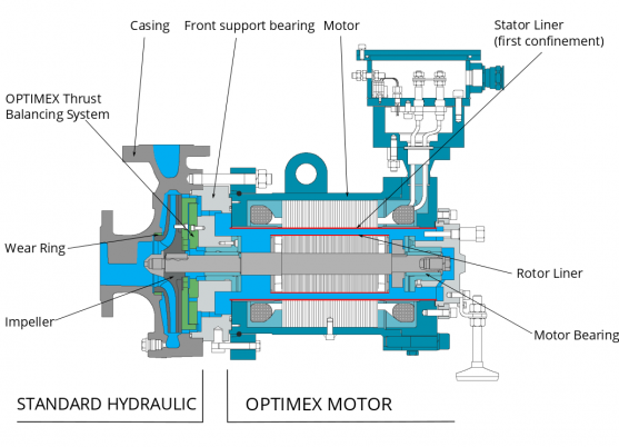
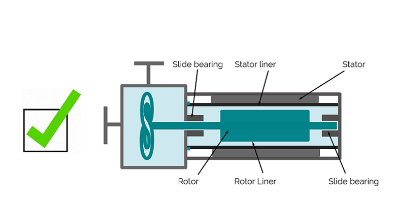
A canned motor pump is composed of a traditional centrifugal hydraulic and a special squirrel cage motor connected in a one piece assembly.
The Canned Motor Pump is composed of a traditional centrifugal hydraulic and a special squirrel cage motor, connected to a special motor through a one piece assembly. The stator is canned in the air gap, confining the liquid in the rotor chamber. The pump liquid circulates through the rotor chamber, cooling the motor, and lubricating the slide bearings that support the rotor. The casing of the chamber forms a sealless enclosure that confines the liquid without any dynamic sealing.
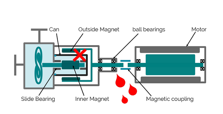
Moreover, in case of stator liner rupture, the liquid remains confined in the motor’s shielded shell (able to resist to explosions), and thus cannot leak externally. It is what we call the double security or double confinement. This gives the sealless canned motor pumps a decisive advantage against the magnetic drive technology which, in case of air gap hood, presents an immediate external leak.
Finally, the mechanical simplicity of the one piece canned motor pump, gives it many important technical advantages: Mechanical balance, Space benefit, No alignment, Low maintenance requirements, Silent functionning, Operationnal in explosive areas, Easy & effective surveillance, Various possibilities of motor cooling systems …
ADVANTAGES OF THE SEALLESS CANNED MOTOR PUMP TECHNOLOGY:
- A double seal barrier = 100% leak proof !
- No mechanical seal = optimal MTBF.
- Low maintenance costs, long running life.
- No expensive and complex lubrication or cooling
systems necessary. - “One-piece” design = gain of space.
- Low sound level.
- Easy to assemble and disassemble.
- No clamping tie-rod (security in case of fire).
- Interchangeability: a given motor can be adapted on any hydraulic.
- Complete Flushing by the flushing hole, without disassembling the pump.
- Hydraulic balancing of the axial thrusts.
- Automatic degassing.
- Stator liner not submitted to the traction efforts created by the pressure or by differential dilatations.
- Intense circulation of the liquid in the motor, allowing an effective cooling.
- Possibility to install on the pump a liquid presence and/or a temperature sensor.
Mag Drive Principle
MAGNETIC DRIVE PUMP CNM
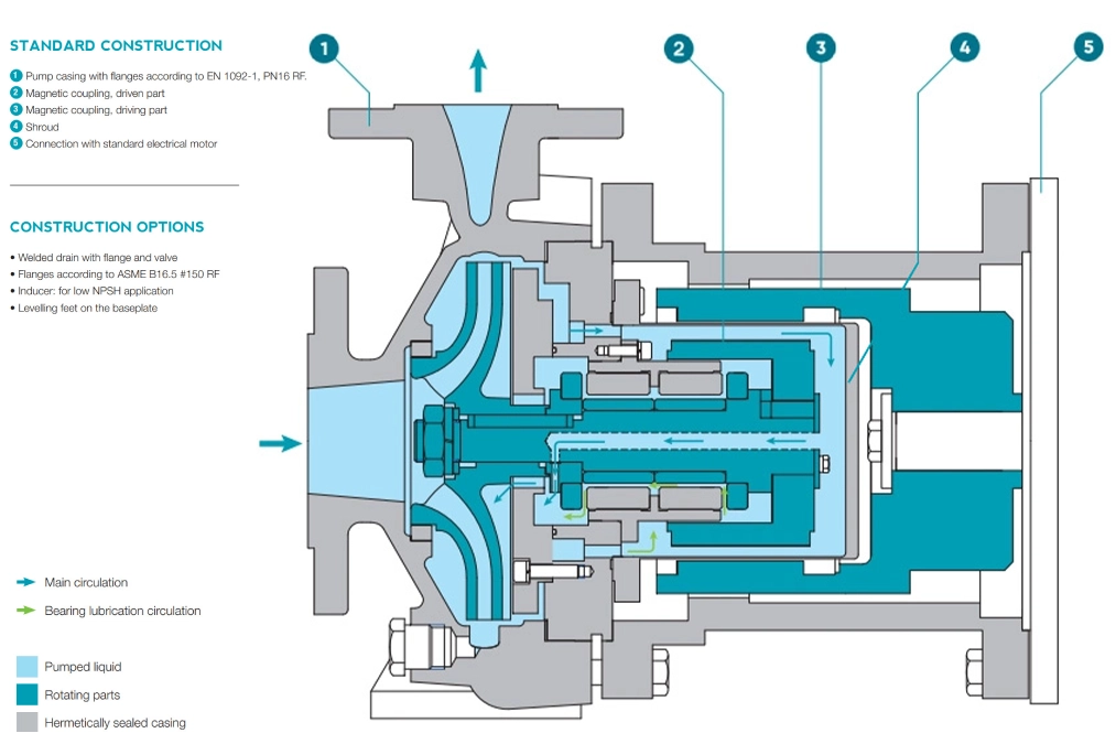
OPTIMEX is specialized in leak-proof pumping solutions to guarantee the security of the process. Naturally OPTIMEX has developed its know-how in the canned motor pump technology. Thanks to their double containment, this technology provides an absolute tightness with no leakage to the outside. The monobloc construction of these machines and the absence of any dynamic sealing ensure the highest level of security against the risk of leakage.
In addition to the range of canned motor pumps, Optimex has developed a new range of magnetic drive pumps dedicated to the chemical industry which includes all sizes according to ISO 2858.
Our OPTIMAG range of magnetic drive pumps has been developed for use in severe applications and provides a very high level of safety due to its seal-less design.
Sized according to ISO2858 chemical standards, the CNM range can replace all other standard pumps, even sealed mechanical pumps, standardised pumps and even pumps with mechanical seals.
We meet the intrinsic flexibility needs of our customers’ applications.
CONSTRUCTION
- Construction standard: ISO 15783.
- Monobloc version: Pump body according to ISO 2858
- Frame version: Pump according to ISO 2858
MATERIAL
- Stainless steel 316L – Hastelloy C4
- Magnetic drive: Cobalt Samarium
FUNCTIONNING AT
- Flow rate: up to 300 m3/h.
- Height: up to 140 m.
Circulation Canned Motor Pumps
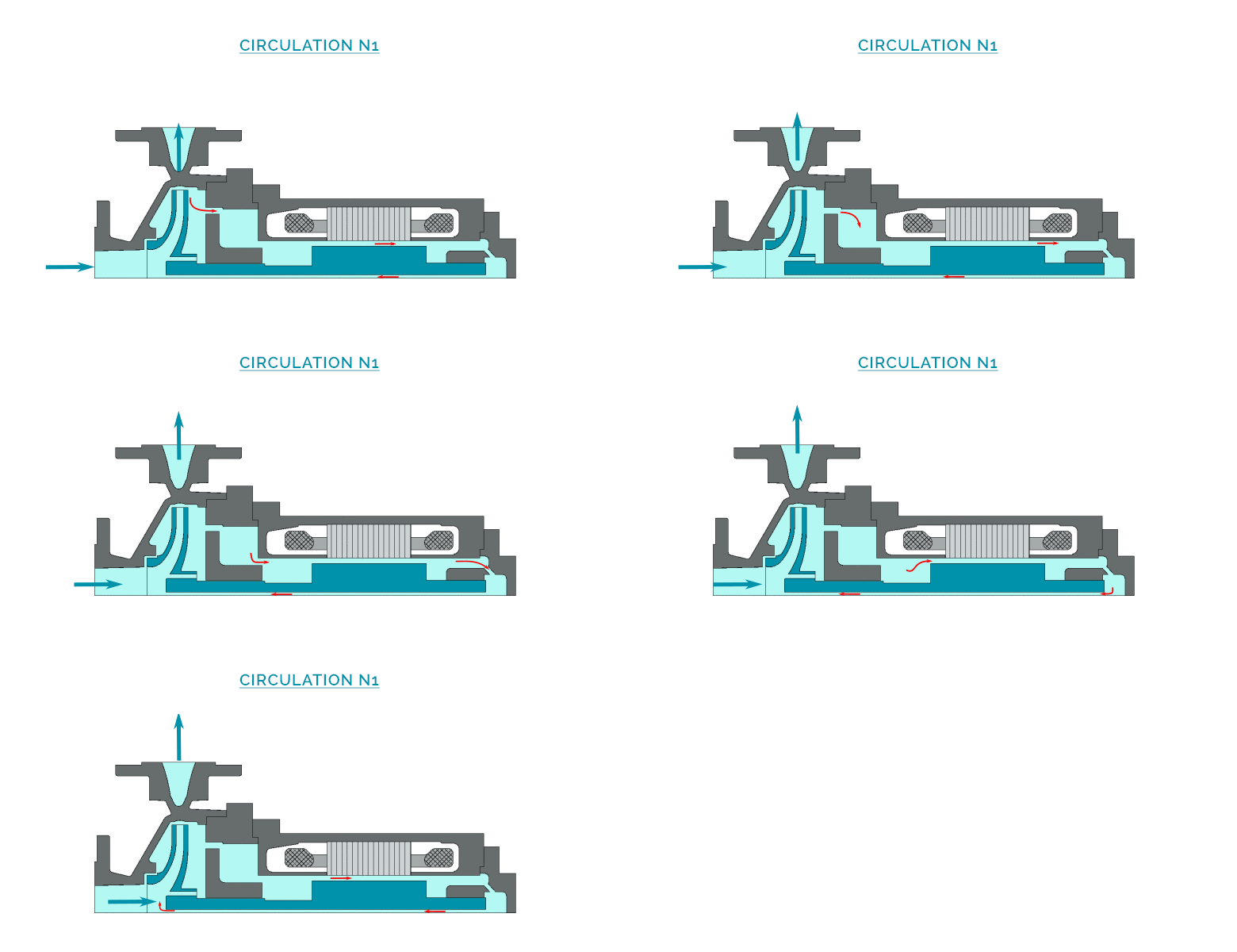
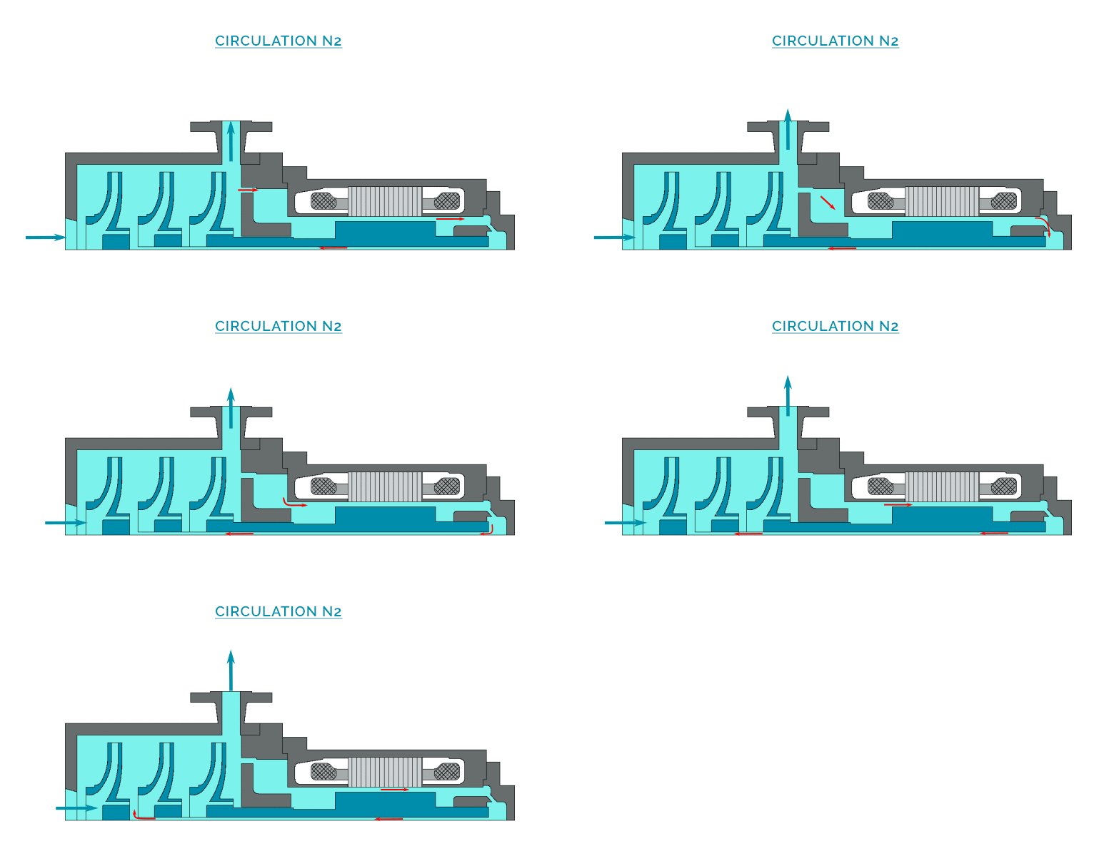
OPTIMEX CIRCULATION PLANS ACCORDING TO API 685
OPTIMEX has established 4 main categories to designate the circulation of the pumped liquids in the canned motors.
In order to complete the designation of the API 685, OPTIMEX established its own designation (with the letter of the category followed by a number).
The table hereunder defines, from the table on the right, the circulations most commonly suggested to our customers.
On demand, we also propose a bigger variety of circulations, depending on the pumped liquids.
|
CATEGORY |
LETTER |
PUMPING TYPE |
|---|---|---|
| Normal | N | Clear liquid, non boiling, hot or cold |
| Overpressured | S | Clear liquid, boiling, hot or cold |
| Cooled | R | Clear liquid, hot |
| Filtered | F | Loaded liquid, hot or cold |
PRINCIPLE DESIGN
DESCRIPTION OF THE CICULATION
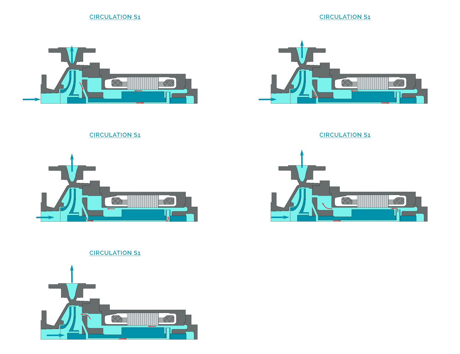
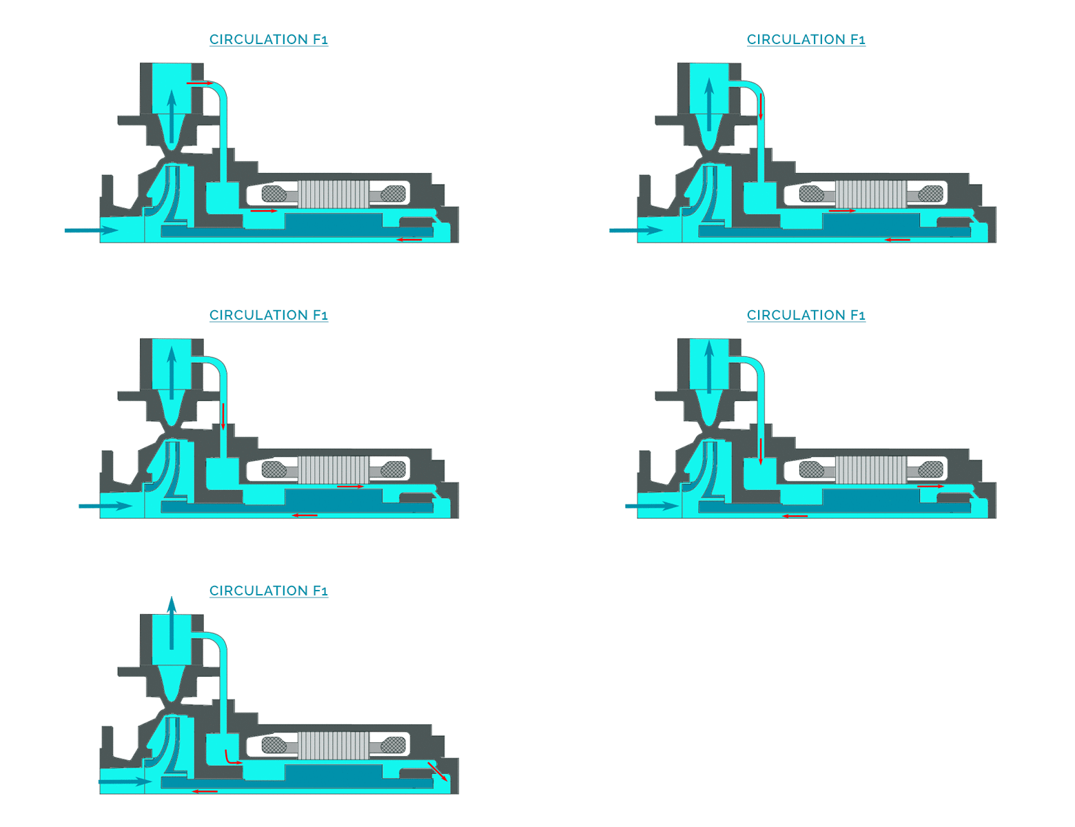
Injection in the motor from the hydraulic casing (at the impeller periphery), passage through the hollow shaft, overpressure by an auxiliary impeller, circulation through the gap and return in the hydraulic casing at the impeller periphery.
OPTIMEX REF.
S1
API.685 REF.
Designation 1-SD
LIQUID IN THE MOTOR
Pumped liquid
PRINCIPLE DESIGN
DESCRIPTION OF THE CICULATION
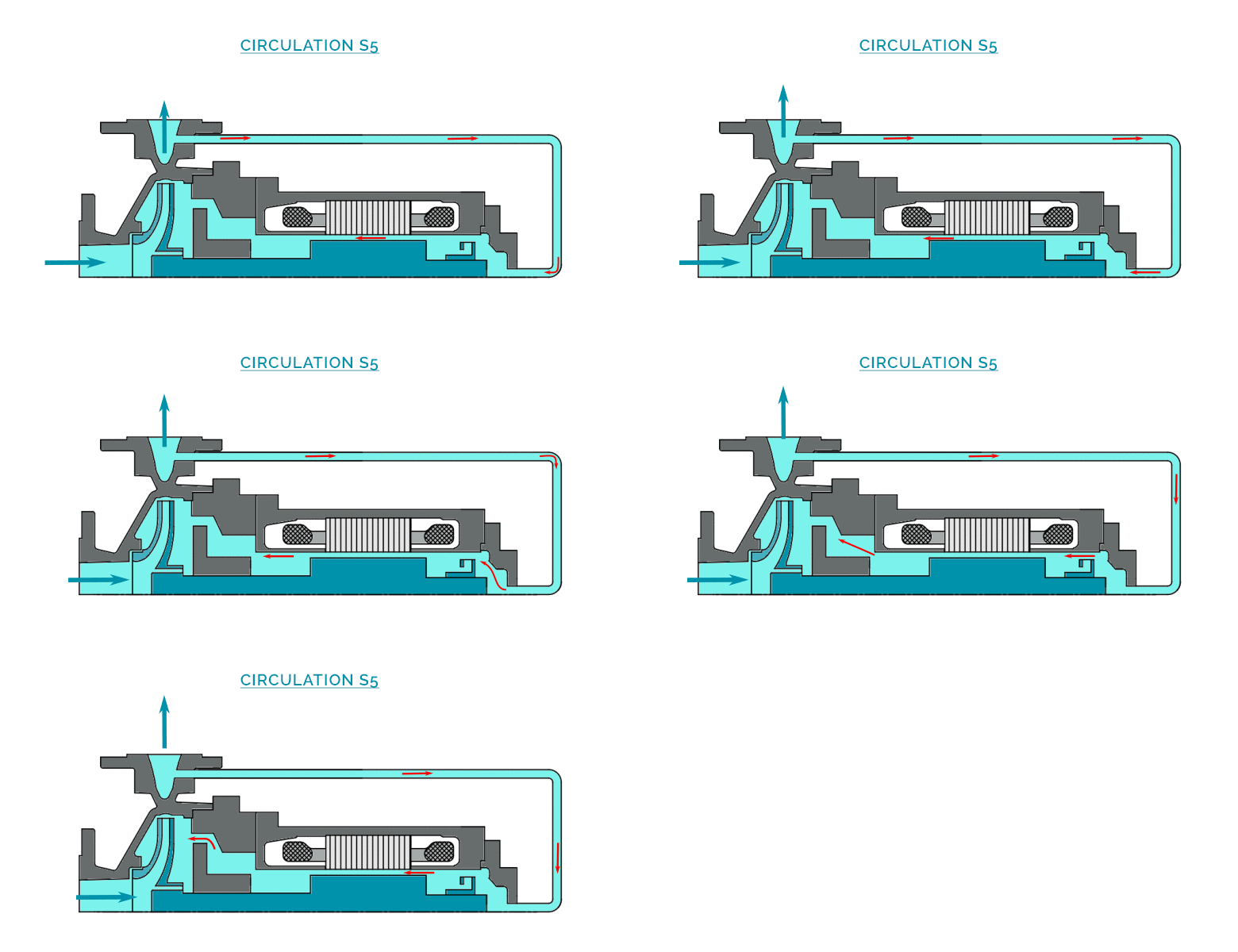
Injection in the motor via an external pipe from the discharge nozzle, overpressure by an auxiliary impeller, passage through the gap and return in the hydraulic casing in high pressure zone at the impeller periphery.
OPTIMEX REF.
S5
API.685 REF.
–
LIQUID IN THE MOTOR
Pumped liquid
PRINCIPLE DESIGN
DESCRIPTION OF THE CICULATION
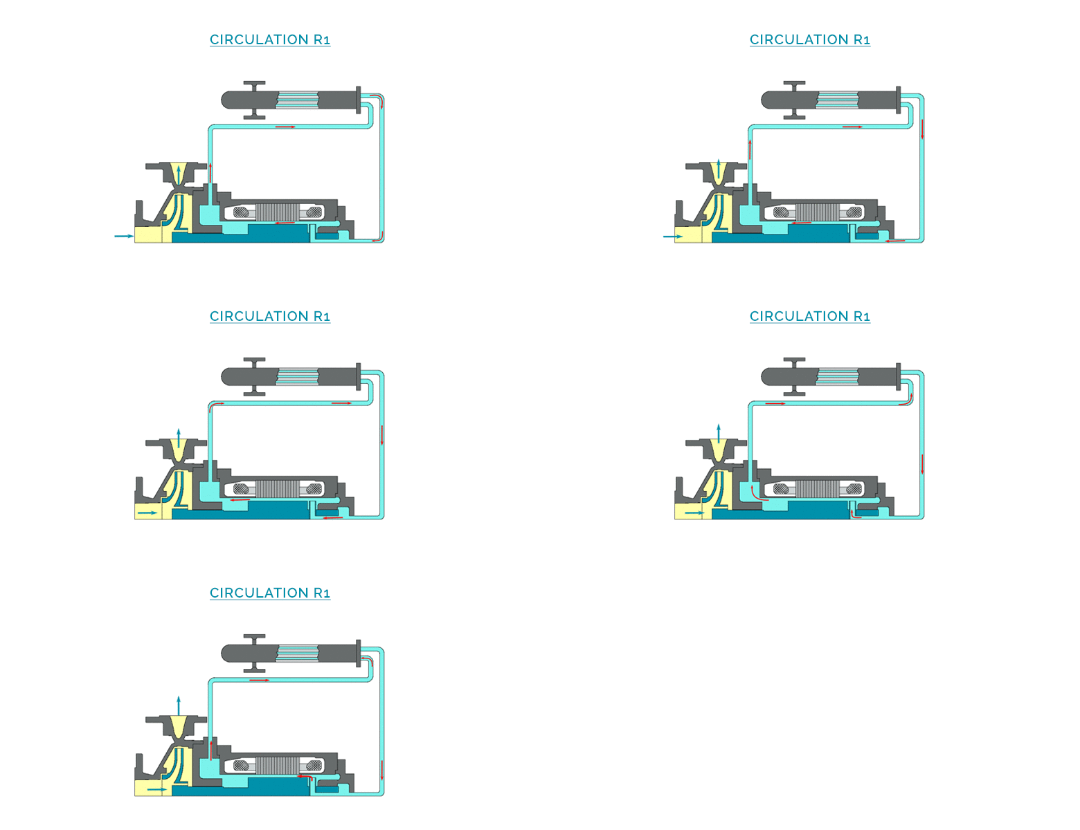
Pumped liquid and motor liquid are identical and they slightly communicate in order to establish an equipressure between the 2 areas (high and low temperature). On the motor side the liquid circulates in an external heat exchanger, flow is established by an auxiliary impeller. A thermal barrier is built between the hydraulic casing and the motor (air or water).
OPTIMEX REF.
R1
API.685 REF.
Designation 23-S
LIQUID IN THE MOTOR
Pumped liquid
PRINCIPLE DESIGN
DESCRIPTION OF THE CICULATION
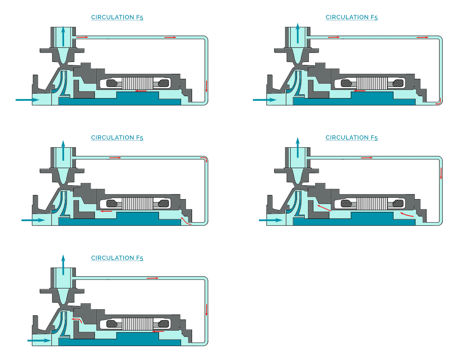
Injection in the motor from the discharge nozzle through a self-cleaning tangential filter, overpressure by a large auxiliary impeller, passage through the gap and return in the hydraulic casing in high pressure zone at the impeller periphery.
OPTIMEX REF.
F5
API.685 REF.
–
LIQUID IN THE MOTOR
Pumped filtered liquid
PRINCIPLE DESIGN
DESCRIPTION OF THE CICULATION
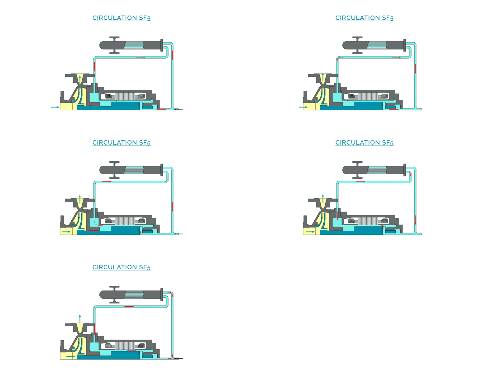
The liquid in the motor and the pumped liquid are compatible and communicate just slightly. A liquid circulates in the motor in a loop on an exchanger (flow is created by an auxiliary internal impeller to the motor). In order to avoid a pollution of the liquid in the motor, we inject a very low flow in the motor circuit from an external source (leak in the pump casing). Injection flow and pressure are determined by OPTIMEX.
OPTIMEX REF.
F4
API.685 REF.
Designation 53-S
LIQUID IN THE MOTOR
External liquid
PRINCIPLE DESIGN
DESCRIPTION OF THE CICULATION
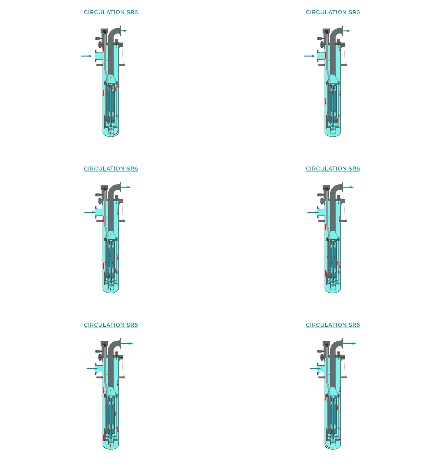
A part of the liquid called « process flow » is discharged through a double casing around the motor, in order to evacuate the calories externally, and to complete the cooling of the internal circulation. A second part of the liquid is injected in the motor from the hydraulic casing (at the impeller periphery), then circulates through the gap, and is re-injected to the process flow at the front support bearing.
OPTIMEX REF.
SR6
API.685 REF.
–
LIQUID IN THE MOTOR
Pumped liquid
Pump Comparative
COMPARISON OF DIFFERENT CENTRIFUGAL PUMP TECHNOLOGIES
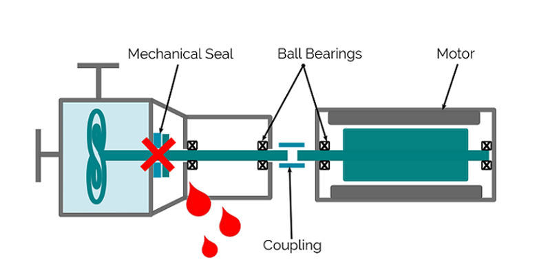
On principle, a centrifugal pump pumps a liquid by forcing it through an impeller while giving it a rotating motion and thus a hydraulic power. A centrifugal pump hydraulic driven by a standard motor must have at the end of the shaft a sealing system. Yet, 75% of the pumps’ failures are due to mechanical sealing.
A pumping system that does not have a dynamic sealing is thus very attractive for the users of dangerous, toxic, unstable, expensive, radioactive liquids. Amongst the totally leak proof pumps, the canned motor technology completes the “magnetic drive” technology. But the canned motor design presents crucial advantages in most applications allowing a higher level of security and reliability. It is the culmination of pumping systems research, and the safest solution allowing an absolute sealing, in accordance with the CE compliances regarding environmental pollution.
COMPARATIVE OF CENTRIFUGAL PUMPS
PUMP WITH CANNED MOTOR
1) Security:
- Totally hermetically sealed assembly (no dynamic seals)
- With double containment in case of stator liner failure
2) Reliability:
- Best MTBF (Mean Time Between Failure) of centrifugal pumps
- Maximal limitation of wearing parts
3) Simplicity:
- Assembly without alignment
- Easiness of preventive maintenance operation
PUMP WITH MAGNETIC DRIVE
- Can failure > immediate leaking to the atmosphere (simple containment)
- Impeller blocked > external magnets continue to rotate > explosion risks
- Temperature monitoring difficulties at the hottest spot (no access at the rear)
- Alignement difficulties of the parts on baseplate > cause of rapid wear


